|
|  | |
| Search |
|
|
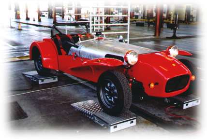
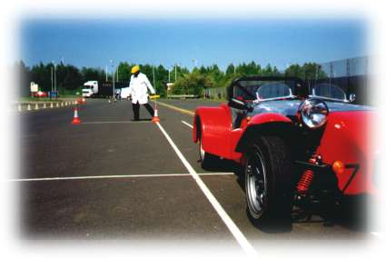
Bob Fenton's car was recently the first Locust to pass the SVA, here is Bob's build report.
A friend of mine bought a set of Locust plans back in 1986, but like so many sets of plans they languished at the bottom of a drawer somewhere and never got built. One day we were chatting about kit-cars in general. He mentioned that he had a set of TJ plans for a wooden - bodied car. Being a boatbuilder by trade, I was intrigued with the idea that the 'offcuts' from the boats I build would go a long way to making a body. However, when it came to it the sizes and thicknesses did not work out. I needed to buy some fresh material. I had been sold on the idea of using plywood, but I learnt that MDF would be suitable if was of the exterior variety. Having never used the dreaded MDF, I thought I would give it a go - just for a change. The 'so called' 'Manual' that came with the plans was the original TJ production. I contacted WRV to see if (a) the plans would still 'work' and (b) if a more informative manual was available. The reply was 'Yes' in both cases. The manual still leaves quite a large number of things unsaid. I suppose this is half the fun of doing it this way, as you really have to work the details yourself. I was concerned to read that the use of PVA glue for construction and waterproofing was recommended. I reasoned that Marine adhesives and coatings would make a better job. I used what I make my boats with. This is known as W.E.S.T. This stands for Wood Epoxy Saturation Technique.
WEST is a liquid epoxy, like thin Araldite. When it is mixed with the appropriate hardener it can be used to glue things and coat them to make a 100% waterproof job. When glueing, a powder is used to thicken the mix so that it does not get squeezed out of the joints or run away.
The beauty is that it will act as a filler when the fit is not as good as we might hope. It is a very forgiving stuff, but it doesn't like temperatures below 10 degrees OR it won't set. I had planned to spray paint my Locust. The WEST epoxy coating can be flatted down to make a good surface for spraying. Standard cellulose is fine over a unviersal flexible primer. The idea of using alloy angle on the corner joints did not appeal at all. When I build my boats, I use the epoxy, suitably thickened, to put a 'fillet' in the corner of every joint. I have done my own tests on the strength of this sort of joint and have absolute faith in the method. (I have been out in some very unpleasant seas in my own boats and the hull joints have never been a worry).
The epoxy fillet makes a neat and easy to clean interior and takes away that 'Meccano kit' look when angle is used. I am also sure that the epoxy method is just as strong. It is also MUCH QUICKER. There is a down side. Cost. However, bearing in mind that it has so many advantages the percentage cost of the Epoxy compared to the total cost of the car is not so bad. WEST is so good that you could take a large brown paper bag and soak it in the stuff; when set it would make a perfectly adequate boat; or if you bolted wheels on it - a car! Tools. If you don't have a cordless drill / screwdriver - get one! I use several that I have collected over the years. Nevertheless, even with one, the time and effort you will save is tremendous. Get the special bits that drill a pilot hole, clearance hole and countersink all in one go. Then use Posidrive screws and put them in using the torque control on the drill so as not to over - tighten. If you are screwing into the edge of the MDF, don't put a screw any closer than 40mm from the 'end' of the material or it will split. (Not the end of the world as WEST will glue it as good, or better, than new). A word of warning. If a screw is put into a 'Wested' joint you will never get it out again once the glue has set, unless you apply some heat down the shaft of an old Phillips screwdriver into the head of the screw. Paper patterns. I didn't glue the patterns down to the material, but rather pricked through the vital points and then checked them with a few measurements. I reasoned that the patterns would come in handy when interior panels needed to be made. An advantage of MDF is that, as it has no 'grain', you can place the patterns in any direction on the board and thus be very economical The cutting out was done with a jigsaw, although I am lucky enough to have a large band - saw which can cut the angles required on some pieces. There has been some adverse press about the carcinogenic properties of MDF dust (from the Phenol in the bonding agent) so I think it is wise to take some sensible precautions when using this stuff. (The same goes for WEST; wear a face mask when sanding and gloves when glueing. Some people are allergic to these chemicals rather like the problems with GRP work. Some are just allergic to work). Building the Body. If you follow the manual, you won't go far wrong. I don't have much to add on this score except that the way I made the corners between the back panel and the flanks differed from that suggested. I use a kind of very flexible plywood in my work. The stuff is 6mm thick and will take bending to the radius on the back corners of a Locust with ease. To allow the plywood to come flush with the outer surfaces it is necessary to rout a step on the back panel and the flanks. It is very easy to do and the Epoxy will bond the 'bendy ply' to the panels and make a strong job.
When boatbuilding, I often use a gizmo called a 'fairing board'. This is a strip of 6mm plywood about 800mm long (or longer) and the same width as the roll abrasives. A handle is glued and screwed to each end in such a way that a strip of 40 grit abrasive is stretched along the bottom of the board, and trapped under the handles. Using this giant sanding block you can 'fair-in' the top and bottom so that the compound angles all blend in correctly before you put the corner filler in. The fairing tool is also handy to fair up the filler that may have been used at the bend in the side flanks / valences. (Incidentally, I did this joint with dowels and a reinforcing of several layers of 200gm woven glass cloth, all epoxied on, just like GRP work)
I had seen several Locusts where the nose -cone overlapped the side valences. It did not look too neat, so I routed a step in the valence the same depth as the thickness of the GRP. Using DZUS fastenings with the anchor plates epoxied into the valence it made a neat job. The level of the surface of the valence and the nose will now be the same.
When the dash panel, nose- cone and the scuttle were all in place it was clear that something was not right. Boatbuilders do a lot of work 'by eye' to see if the complex compound curves of a boat are 'fair'. By using a 'fairing batten' (a long thin piece of wood about 10mm x 25mm section) placed along the line that the bonnet would take to join scuttle ,dash panel and nose-cone in one 'fair' sweep, I could see that all was not well. Using the fairing board it is possible to alter the radii and angles of the scuttle and dash panel so that it comes right 'by eye'. If you take this path, you will find that the radii of the top corners of the nose-cone will differ from the scuttle and dash panel. When you come to make the bonnet the bend in the bonnet will not be a simple curve, but will be a changing radius along its length. To produce such a curve it is necessary to 'wheel' the bonnet so the changing radii will match up with the scuttle and nose - cone at either end. I'm fairly sure that some compromises have been made in the design of the plans in this area to keep things simple. However, I believe that to get the line of the bonnet / scuttle / nose-cone right it is necessary to step back and look carefully at the line these should take. This would also have implications for your windscreen frame fit. If you use MDF it is possible to put a neat radius on the top edges of the body to replicate the shape of the original Lotus. Using a bearing guided rounding over cutter in a router you can put a super rounded shape to all the necessary edges and get away from the idea of bending 'D' alloy round the edges. This, unless it is done with great care, looks a mess. Add a couple of coats of epoxy and flat off -you are ready: to spray. I also made the following modifications as I went along to make access easier and to bring the handbrake to a more ergonomic position.:- The top face of the tunnel was cut down to make a step where the handbrake fell naturally to hand, and a welded - up ladder - frame arrangement fitted in the gap between the two sides of the tunnel. This provided a mounting for the gear - change (sawn off the gearbox and repositioned) and the handbrake with its necessary cable anchorage. The whole lot is held by countersunk machine screws through the tunnel sides which are tapped into the frame. An access hole for the reverse light switch is a good idea while in this area.
A large access hole was cut in the gearbox side of the driver's footwell. This gave better access to the pedals and the end of the well. But as I skinned the gearbox side of the opening with the alloy sheet, it gave 3/4" more foot room in an area where every fraction of an inch matters. I cut a similar hole right over where the petrol tank and sender unit would come and followed the advice about making extra clearance in the prop-shaft area next to the driver's seat as 'per the manual'. It might be of interest, at this point, to explain about my workshop where I build small sailing boats. The building has a fair sized ground-floor workshop where the boatbuilding goes on. It has two rooms upstairs, one of which is set aside for 'clean' work like varnishing spars etc. The front room became the home to the Locust build. in a space only a little longer than the chassis and about 8 feet wide. Access is through two doors of normal house dimensions. However, some friends and I got the chassis upstairs at an early stage, while at the same time bringing the mechanical side along. I could not fit the engine as I was worried about the weight on the floor of an ancient wooden building! I knew that one day the whole lot would have to come down again. However, it enabled me to carry on working on the boats and still do some 'overtime' on the Locust. The temptation to work on the car was too much sometimes and I'm sure work suffered as a result. Later a quiet time in the boat building business enabled me to bring the pieces down again and reassemble them in the larger workshop - what luxury! By this time I had the rolling chassis sorted and enough done to move it to a rented garage not too far away. The rolling chassis. Much of this was standard stuff - Ford GT X-flow with Escort sport box and MKII axle. I did use the WRV front wishbone assembly and this caused much messing about. I reckon that to avoid bump-steer the plane of the steering rack and the ball joints on the track-rod ends should be the same ie horizontal at normal laden weight. When the wishbones were assembled it was clear that the coil - over top mounting would need raising to, in effect, lower the suspension and give a horizontal aspect to rack, steering arms and wishbones. They all ought to rotate about a 'common centre', which I feel is impossible in practice. But a close approximation is needed to avoid bump steering. I chopped away most of the top mounting and made extension plates which would give me a choice of locations for the top bolt. Eventually it all came right. The mounting for the forward wishbone mount, which has to be welded on to the chassis, is a flimsy affair. I wish the gauge of the metal could have been a bit greater to inspire more confidence, but I am sure there is enough strength there - just. When welding these on I was concerned that all the centres for the inner pivot bolts would be in line. I did this by putting a steel rod through the existing holes and then aligning the extension brackets on that. I'm sure it wouldn't do if these mountings were out of line. It is worth taking a little care.
Demands of the SVA test suggest it would be an excellent idea to weld captive nuts on the chassis at an early stage so that the seat - belt mountings comply. 7/16" UNF is the size. At the rear end I discovered that the ride height was too high and I wanted to lower it to reduce the gap between the wheels and the arches. After much thought I took the body off and cut away all the original top mounting. I replaced it with a fabricated welded - on turret which goes right through the boot floor. In this way, I had about 2" to play with in terms of adjustable ride height. In my opinion it makes the car look better. Life is never simple. I discovered that the rear suspension geometry allows the 'nose' of the diff to droop the higher the axle is raised relative to the chassis (which is what happens if you lower the car). To counter this, I needed adjustable top links (trailing arms), so I chopped them in two and added a thread to one end and a captive nut to the other. All were carefully welded and with lock-nuts the scheme did what I had hoped - the diff can be brought level again. Wiring and lights. Just because a Locust can be cheaply built, it does not follow that it needs to be badly built. One area where I think it is worth spending some money is on a custom made loom. A friend with a similar vehicle used a 'butchered' Escort loom without unwrapping the whole thing to remove redundant cables. The result was that the car caught fire. Several firms advertise looms -so shop around - or take the time and trouble to study cable current capacities and do the job by starting with fresh cable - or unwrap and get rid of potential hazards. A neat loom, well clipped back, does wonders for the perceived impression of the vehicle especially now that the SVA test is upon us.
If
you think ahead, connectors can be put in at the front end so that
headlights, indicators etc can be removed easily. The SVA testers
are no longer looking for 'E' markings but the height and position
of all lights needs to comply with the 'regs'. 'Kit Car' produces
an excellent guide to the SVA and I found all the info in there.
The car passed first time, so it has proved to be a useful guide
at a fraction of the cost of the Official Manual. Pedal Box. My wife bought me a book about the Lotus 7 as a Christmas present so I spent the day designing a pedal box which was based on a photograph (better than watching bloody television!). I never was happy with the idea of using the Ford offering and the Triumph stuff was not too easy to get hold of at a sensible price. I used Escort pedals but re-positioned the pivot points by chopping them into slices and rearranging the bits.
The standard item has the pedal pivot at the top and the push rod pivot below: what we need is the reverse of this to enable the push rod for the master cylinder to act above the pedal pivot. If you use the original pivot bushes and pins you can end up with an item which should be reliable and offer the chance to re-bush things if they wear.
Steering. The normal Escort column and rack were pressed into service. A friend of mine told me to be careful when extending the lower column with a tube as the welding is critical as well as the method. Some of the material will be high tensile steel which has been heat-treated and really does not like being welded. Also, if you just cut a tube 'square' to slip the shaft components into for welding, the weld forms a 'ring' of weld and considerable heat all in one location on the HT material.
I was told to cut the tube to create a 'Birds - mouth' joint which has the effect of doubling the amount of weld which can be applied and spreading the heat over a longer amount of shaft. Also, if the weld does fail, the two components are still 'locked' together and cannot rotate easily - perhaps giving you some warning that your steering wheel is about to part company with the rack. I was convinced. The Engine. I had the Ford X - flow lurking in my garage for 17 years. It had seized up when I came to inspect it. One of the plugs was out and that bore had gone rusty. A dose of diesel down the pot eased it off and I thought all would be well. It wasn't. I really should have taken the trouble to strip the whole thing down, as when I came to start it, it didn't want to know. So, out came the engine for an investigation. I found that all the piston rings were 'welded' in their grooves, and that the sump contained a semi-solid mass of yuck, which if it had ever got into the oil -pump would probably have caused it to burst. New rings, after a glaze busting session, and a good clean out of the oil system did the trick: it didn't go first time, but near enough. I acquired a set of DCOE 40s jetted for a 1600 motor. If you buy these second hand I suggest you take the covers off the float chambers and inspect the brackets which hold the float pivot pin in place. One of each pair on my carbs was broken as I discovered later. To mend them is not impossible but it involves fiddly riveting. However, spare tops are available (at a price) so all is not lost. The Weber linkage mechanism which is designed to allow the cable to come in above or below the carbs is a god bit of kit in my opinion. What I can't understand is the high price charged. However, what it does is amplify the amount of pedal movement so that a tiny movement of the throttle translates to quite al large movement at the butterfly. If you look closely at any modern car you will find that the amount of throttle pedal movement is small - it makes for happier driveability and control. I had to use the linkage which uses bottom cable entry, but things get congested in that area if you are using the mechanical pump. A
Ford top - entry distributor will just fit under the carbs (depending
on your manifold) but a Fiesta Bosch type is better and can be fitted
with a side entry distributor cap. It also gives you electronic
ignition. I don't have any vacuum advance and it seems OK. I found
it necessary to chop the oil filler off the rocker box and weld
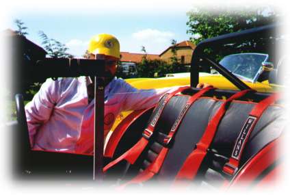
it at the aft end so that it cleared the bonnet. Right from the start I had aimed for a 'four wheeled motorbike' concept so I have little intention to fit a hood. 'Brooklands' screens were fitted and then some thought was needed on seating. As I reasoned that as everything would get wet, the seats would have to be capable of drying out. GRP shells were a possibility but they looked a little uncomfortable. So I settled for the traditional squab and backrest design a -la the original Lotus 7. PVC upholstery would trap the water in the seating foam, and past experience of owning leaking sports cars told me that mould and smell would be the result. Leather is really the only option and I was lucky in that the guy who makes the bunk cushions for my boats happened to have half a hide of super black leather. The foam was placed on Marine ply backing boards which I sealed with -you've guessed it- Epoxy! Now, if the seats get wet I'm hoping that the only detrimental effect will be a damp backside as the leather is able to 'breathe' (unlike PVC). Heavy duty 'Velcro' holds all the seating in place held down with contact adhesive and Monel staples (which won't rust). The SVA examiner was happy enough that this was a secure fastening for the seats. It also enabled him to quickly inspect the lower belt mountings. Upper seat belt mountings are more problematic. The design of the Locust body does not come high enough to bring the top mounting at a level where a tonneau could cover the belts and still comply with the 'regs'. The top mounting has to be above the body line and thus the belts would poke through the cover. I anchored the top of my 4 point belts to a bar welded across the roll bar just at the level of the body. This is too low. So a bolt-on belt guide was made to raise the effective height to that required by the 'regs'.
This part was fixed to the back rest which I had extended upwards from the position shown in the plans. Now the car has passed the SVA it would be possible to go back to the original height to allow a tonneau to fit over the load area and seat belt mountings. You can test the mounting height by making a test block and gauge stick as described in the 'Kit Car' SVA guide. You are looking for a height from the seat 503mm to the top mounting (or EFFECTIVE height) at a point 136mm forward from the backrest at squab level.
Building the car started in mid 1996, and the SVA test took place on the 28th April 1999, so I guess that three years is the time it has taken to finish the job. It has not seemed a long time. I have enjoyed every moment - yes - even the SVA testing procedure.
Like everyone else, there were periods when nothing got done due to lack of time, or lack of money. I'm glad I chose a locust because it represents more of a challenge than merely bolting a kit together. The resulting satisfaction is so much the greater. If you are in the middle of a build I wish you well - keep going and watch the quality. It's not worth rushing or bodging the job. Bob Fenton
| ||||||||||||||
|
|
||