|
Having
now cover over 2500 miles in AFG 486S,
in one year since it passed the SVA
Test, it was now time to modify some of
the electrics that had give some
trouble.
The first of which was
the original fuse box which I have
used from the Escort MK2. This caused
and total power failure on the
winkers, instruments lights,
stoplights etc. on a run out one
evening.
The fuse box is made of
plastic, with copper fuse holders. The
problem is caused by corrosion between
the holders and connecting pins
riveted through the plastic holder and
you cannot solder or fix it in any
way. The only solution is to scrap the
thing and obtain a new one (rare as
rocking horse poo) or a second-hand
one.
A trip down the local
Ford breakers was in order. They had
six in their bin, two of which were
wired up differently underneath. The
remaining four were the same type as
mine of which only two was good. The
other two had the same problems as
mine so I bought the two goods ones
for a total of £10.00
Back home I plugged the
new fuse box in and have no more
problems up to date.
The second item I wanted
to change was the contact breaker
system on my Ford Crossflow 1300
engine.
On the Bucket & Spade
run in June, the engine had started to
miss-fire and on investigation the
points had closed up. Time to upgrade
to a electronic system.
Looking through the
magazines, they range in all prices
and I remembered an article in the
LOCUST Mag on a Maplin product for
about £ 12.00. I did look at the
product but felt I could go one
better.
I scoured through my
books on Ford parts and found that
Ford went over to electronic ignitions
round about 1981 on the Escort. The
Mk4 1300 Escort’s has got a nice Bosch
electronic ignition, not on a CVH
engine, but on a Valencia engine which
is very similar to the Crossflow
fitted to the Mk 1 & Mk2 Escorts,
Cortinas and Capri’s.
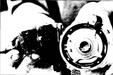
They are the type with
the amplifier mounted on the side of
the distributor body as in the Fiesta
1.4,Orion 1.3, 1.4, 1.6, & 1.6i,
XR3 & XR3i.
The only problem which
accurse with the amplifier module is
contact with the main body of the
distributors. Take the two screws out
and clean both surfaces. coat then
with special heat conducting compound
available from your Ford dealers and
screw amplifier back on.
What is good, is the
distributor from these will drop
straight in to the Crossflow engine
with a few minor wiring alterations
and change of coil.
Why do you need a change
of Coil?
If you run a Crossflow
engine using the original Ford wiring
loom, it will be ballasted at 9 volts,
and this will not suit the above
distributors. A standard coil of 12
volts will do.
Back down to the Ford
breakers. After searching around, I
found a nice distributor in a Fiesta
1.4, compete with coil and more
importantly the multi-plug lead and a
decent set of HT Leads, all for the
sum of £ 20.00.
Back at the car and with
the distributor all cleaned up I was
ready to install it.
Off came the rocker box
cover and I turned the engine till no.
1 cylinder was on compression, both
rocker arms have clearance at top dead
centre which is marked on the
crankshaft pulley.
 I I
remove the old
distributor and retained the old
clamping plate as the new one of the
Fiesta was slightly different.
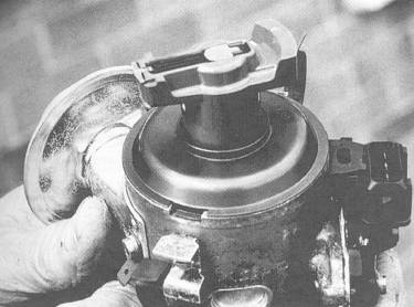
Around the rim of the new
distributor you will find a line or
notch. You can see the notch or line
in the picture at 8 o’clock position.
This is the firing point of cylinder
No. 1. That the front one on the
Crossflow and in case you have
forgotten the firing order for the
Crossflow it is 1-2-4-3. The rotor
runs in anti-clockwise direction as
you look at the top of the cap.
Before you drop the
distributor in, put the rotor arm on
and align the rotor pointing at the
line or notch.
Slide the clamping plate
on and feed the distributor in and
watch how much the rotor turns past
the line or notch. Make a pencil line
on the rim where the rotor is now
pointing. Now make a pencil mark the
same distance away on the opposite
side of the line or notch.
Pull the distributor out
again and turn the rotor to your
second pencil mark.
Drop the distributor back
in and the rotor should stop turning
at the line or notch. You are now on
No.1 cylinder firing position and when
you fit the cap, the rotor will be
pointing at the lead to No. 1
cylinder.
Do not use the lead from
the loom as this is ballasted. Run a
new wire from the ignition switch down
to the positive side of the new coil
(SW15) and join the black wire from
the multi-plug to the same. The green
wire from the multi-plug then fits on
the negative side of the coil with a
feed from this, to your electric
rev.counter if you’ve got one fitted.
The third wire is brown and goes to
chassis earth.
All ready to switch on.
The distributor should be fairly
accurately timed up to start the
engine and when running at tick over (
850-900) a setting between 6 degrees
before TDC and 11 degrees before TDC
should suit depending on your cam.
A try out on the road and
make adjustments a degree or two at a
time to see how it behaves. If you get
pinking on hard acceleration, then
back the distributor off a degree or
two.
And there you have it, a
electronic ignition system for about £
20.00 for a fraction of the cost.
I did buy and new
distributor car and rotor arm, but
these are peanuts. You may also find,
depending on your manifold that the HT
Leads to your "top entry cap" foul the
manifold but you can buy side entry HT
Leads to over come the problem.
CHRIS LAYCOCK.
|