|
|  | |
| Search |
|
|
The Hamilton build project: part 1
In July 1998 we had just moved to our present address which had a single garage and parking for two cars on the driveway. After doing the usual customary decorating, as you do, my attention turned to the garage, and after watching a friend of mine build a Cobra replica, thought that a smaller project would give me something to do and also maybe get my then eight year old son interested in mechanics as well. In November 1999 friends of ours announced that they were immigrating to Spain for a new start. They had been quoted by the removal people for all of their stuff to be shipped over, which was my friend’s wife’s job. Unfortunately (or fortunately for me !) she forgot to tell them about the Locust project sitting in the garage!!. My friend only realised this two weeks before they were due to go!. To say that he was eager to get shot of it could be a bit of an understatement. The project consisted of : 1 build manual (ha!) and set of plans,3/4 inch marine ply cut out to most of the plans, sheets of aluminium, one 1976 MK11 1300L Escort broken into the necessary bits, complete with registration documents, and a White Rose brochure.
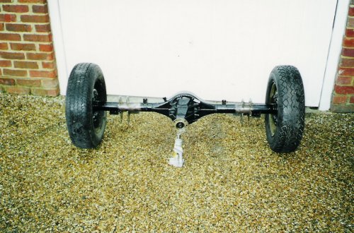
Now, I’m not a complete knucklehead when it comes to cars, as when I was younger I was always working on my cars doing the usual servicing and minor repairs, when you could work on cars without having to plug them into a computer at £60 per go or having to have specialist tools! Ah……the good old days!!. But I could see that this would be a long term project and that this would test my skills(!) to the limit….And possibly my patience and definitely my finances!!!!. On the plus side I knew that I would get a great deal of satisfaction when it finally hit the road, and would be a steep learning curve for me which would maybe bring out some new skills that I didn’t know I had!. I know that this is not exactly the best way to take on a kit, as I had not looked at any other manufacturers or even seen a finished example, but it was too good an opportunity to miss!! Either way ,I knew that it was going to be some challenge!! So here it was sitting in my garage, all of these bits….what had I let myself in for??? Well judging by the brochure White Rose Vehicles were not exactly in the same league as Caterham, and I felt that their price list for parts were a little expensive. So I decided to get cracking on cleaning, inspecting and painting the donor parts, while I saved up some cash! According to the last MOT certificate in 1995 the donor had done 99,000 miles. My friend had driven it and said that he found it fine with no horrible sounds coming from the engine, box or axle, which was good enough for me. I was going to use these as they were to obtain an age related plate. I decided to strip and give the engine a light overhaul.
The Hamilton build project: part 2
During December 1999 I cleaned up the axle and gearbox and gave them a couple of coats of smooth Hammerite and then got down to stripping the 1300 x-flow for inspection, being sure to carefully clean all of the bits and label them in the plastic coin bags that you get from banks which were ideal. On close inspection all seemed well for a 99,000 miler, the cam was okay as were the pistons and bores and even the sump was not as caked up as I thought it might have been, which was all good as it pointed out to me that this car had regular oil changes. The only thing that it needed were new exhaust valves, as the old ones were a little coked up. All in all it was good considering that these parts had been sitting around since they were last used in 1995!!! My bedtime reading had been the Haynes manual, White Rose brochure and the build manual. The brochure estimated an average build using everything from the donor would be less than £2500….yeah right, I thought ,for a start I don’t really fancy using the 1976 vintage wiring loom, and the donor instrument binnacle wasn’t to my taste, and I will have to have something other than those donor wheels!! So it was obvious that the figure that was given must have been for a very basic car, as even if you added up all of the bits that you needed from the company it was clear that they were being extremely optimistic. On reading the build manual it mainly spoke about the building of the body tub which seemed fairly straightforward, but on the mechanical side of things I think it left it pretty much up to the builders ingenuity and engineering skills!. I think I might need a bit of help here and there!!! The only thing that seemed a little worrying was the skinning of the body as I knew that any mistakes here would be permanently on show. I had also started to buy Which Kit? and Kitcar magazines mainly to get ideas and for the small ads. I was now on a mission to get a second hand chassis, cortina front end suspension, wings, basically anything that I could get for my Locust without paying the prices that were advertised in the brochure!!! Meanwhile in the garage I had decided to leave the engine re build until a later date, as I was toying with the idea of adding a hotter cam and ,after seeing the other seven clones in the magazines I really wanted a pair of those 40 DCOES! After discussing this with my mate Bob, who has built a Cobra and a V8 supercharged trike, he was trying to convince me to dump the 1300 and go for a 1600 tuned x-flow, as in the long run I would want to upgrade in the search for more power, so it would be a waste of money to do up the 1300 only to have to spend more and have the hassle of replacing the engine with a 1600 when the car was done. This made sense, but I wanted to wait and see how the rest of the build was going to go until I made up my mind. I was also worried about how this would affect the age related plate. Another thing that I was worried about was the SVA test which had just been introduced. I was certainly not going to finish the build in time to benefit from the exemptions, so this car would have to be totally SVA compatible. At the time I didn’t know whether it was even capable of passing an SVA test!!
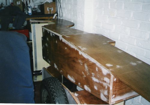
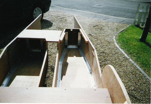
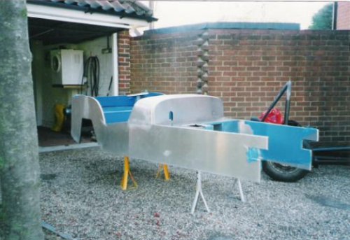
I decided to press on with building the body tub. I took out the plans in order to check my friend’s accuracy with the panels that he had cut out. Unfortunately the driver and passenger floor pans were out and also the side flanks, so it was off to the local wood yard for two 8x4 sheets of 18mm marine ply. The panels that were out were reused in other parts of the body so I wasn’t too bothered. I followed the build manual and plans and decided to strengthen the joins with 1” ¼ aluminium angle (which is standard practice, I later found out) I bolted it to the panels and sunk the nylock nuts below the surface of the ply to be filled in with filler, flush with the outside surface in order for the skinning. I used a building product called Gripfill to bond the joints together this stuff is waterproof and it will stick anything to anything it’s applied with a mastic gun and has the consistency of mastic as well. The only panels that I had real trouble with were the rear floor panel and the rear panel. The plans did not make any sense so I had to go my own way after checking all of the other panels. After I had joined the club I discovered that I wasn’t the only one who had problems with this part of the build, which made me feel better!
You may notice in the photos that the finished body tub did not have an inner or outer scuttle panels, this was because I had intended to use the GRP scuttle from White Rose, but as again, after I had joined the club I was advised to not bother as it had a reputation of not being a very good fit! So I went back and pulled the side flanks off (not an easy task when that Gripfill has been applied!!!) and replaced them, made up the inner and outer scuttle panels and also, while I was about it cut out a section in the drivers side gearbox tunnel to give more room for my feet around the pedals.
It was now early 2000 and I was on the lookout for the parts, any parts for the Locust when I read in one of the magazines that White Rose Vehicles had gone bust!! Was this the end of my build??? The Hamilton Build Project Part 3: The search was now on to find the parts to start the build. I had started to buy the kit car magazines, to aid my search with the small ads. I couldn’t believe my luck when I saw an ad for a pair of clamshell wings for a locust! It was a local number and after a quick chat on the phone, I went round to have a look. The chap selling them was Pete Hudson who since has become a good friend of mine. He had bought his Locust second-hand and was making the change to cycle wings. It was the first time I had seen a locust in the flesh and it gave me the boost I needed to get on with my build. Pete was a mine of information and as my build progressed we were always brainstorming ideas and finding ways around problems, not only with my build, but also his re-build! It was now April 2000 and I had joined the club and felt that I was not alone! I’m not afraid to admit that I was busy taking the best ideas from members cars, to incorporate into my own build! I had decided to go for a 1600 crossflow and to junk my 1300, and I just had to have those twin 40 DCOES!! Also I had set my sights on having Caterham wings back and front and heated screen, and tubular wishbones as opposed to the Cortina front end. All these were dreams at the moment as I only had an unskinned bodytub and a pair of wings! This was about to change though, as I spotted another ad which would give me a fuel tank, bonnet, Caterham nosecone, Caterham rear wings, rear axle brackets and a chassis!. Needless to say, after a phone call, I shot down the M25 to Surrey with my mate Bob and his van and took the lot! It turned out that the chap selling this lot was Brian Keywood’s brother, and the chassis was built by White Rose in 1998, but with modification to the front upper wishbone mountings (mainly beefing up, a thicker tube had been used, as there had been problems with the thinner tube on some cars cracking).
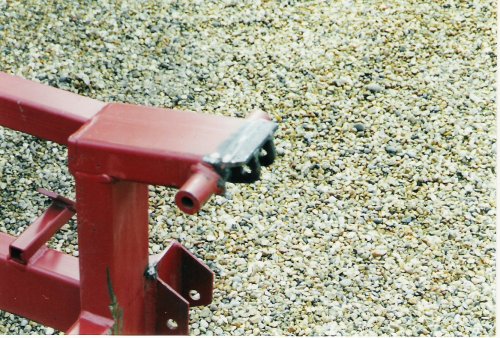
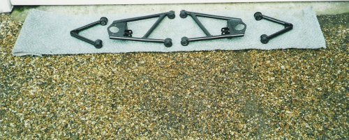
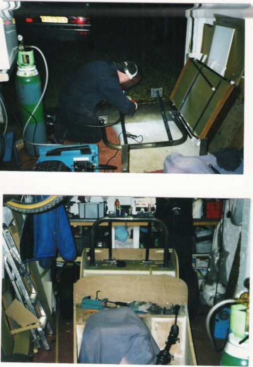
With this lot back in my single garage, it was getting rather cramped! I had the bodytub up on its side and the chassis on axle stands ready for painting. But before I could get the paint brush out there were a few modifications to be made. Firstly the upper front coilover shock absorber brackets would have to be extended so that they would sit in a more upright position to enable them to work more effectively. Pete had a look and came up with a neat extension piece which also had a bracket for the top mounting of the shock. (The photo explains it better than any description of mine!). Pete made two of these at his work as he has access to off-cuts of steel and CNC machinery.
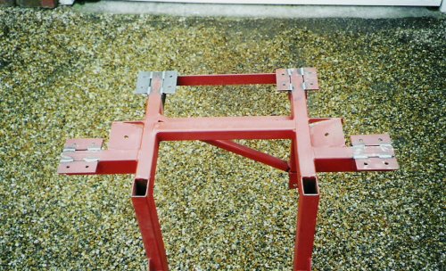
Next was the roll bar mounting plates. The chassis came with the standard three points, but I wanted four, just to be a little different. These were simply made from 3mm steel angle, drilled to match the others (see photo).
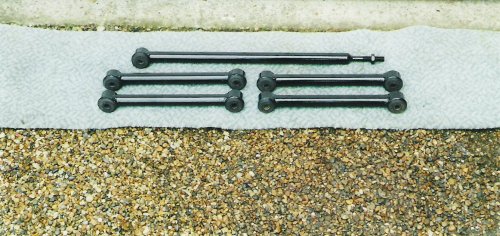
I had also taken patterns of Pete’s panhard rod (oo’er) and rear trailing arms and had given them to Slick Mic, ( Who fabricated my mate Bob’s V8 supercharged trike’s frame), to fabricate.
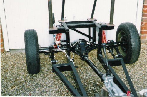
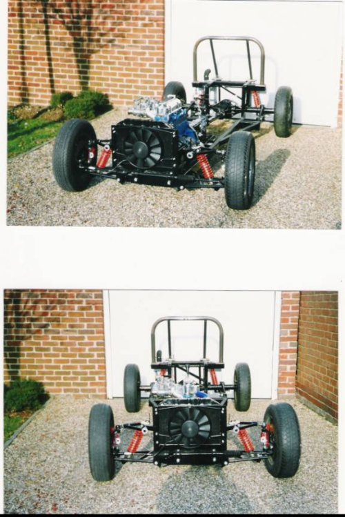
The same was also done for the front wishbones top and bottom and their respective brackets. The Cortina tie bar brackets were removed from the chassis as they were not needed. Now I just needed to find a top mobile welder to weld all of this together and then I could get painting and be another step closer to turning this lot into a Locust! The Hamilton Build Project Part 4: It was now autumn of 2000 and I had heard through the grapevine that BWE had taken over the production of the Locust and Hornet, which was a relief, as I thought that any parts that I might have needed may have been difficult to find. A trip to the Scrap yard gave me the cortina front uprights, hubs and discs (getting rare now!).I decided to get a pair of reconditioned callipers and new discs from Kitfit.I was now on the lookout for a decent welder to put together all of the brackets I had made up. As it turned out Pete knew a welder who lived down the road from him, so I decided to try him out! Jim the welder, as he became aptly known, came round and done a brilliant job! It turned out that he worked for a company owned by my late father -in-laws cousin! Small world! He enjoys working on the Locust as it is different to his normal work of wrought iron gates and fencing etc.With the welding all done my attention turned to painting the chassis, Rear axle, trailing arms, panhard rod and the wishbones. This was all done with smooth black Hammerite,it seemed to take ages but after two coats it looked pretty good. When it had all cured, I could finally assemble all of the parts to give me a rolling chassis.
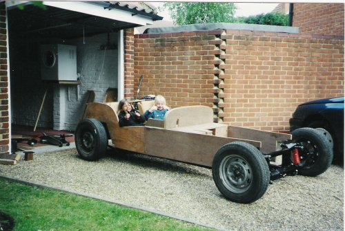
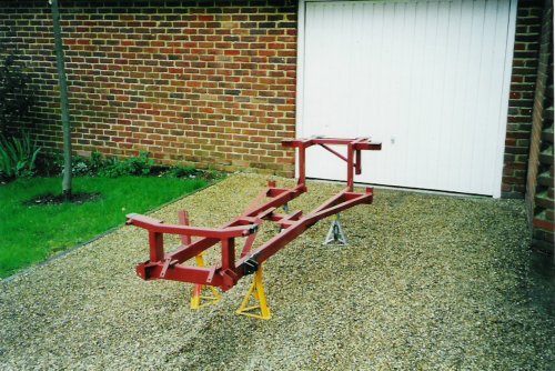
My extensive measuring and checking had paid off as it all went together with no problems at all, the cortina bushes were pressed into place with a home made tool (courtesy of Pete), and with a little spacing the wishbones and trailing arms were bolted into place. The coilovers and springs used were from Dampertech these are fully adjustable. I phoned them up with my requirements for ride height and top and bottom fittings, and they done the rest! They are similar to the, dare I mention it ‘locost’ sets that you see in the kitcar press. The springs are 250lbs at the front and 150lbs at the rear, this is a guesstimate, as I may have to change them later depending on how it drives when it’s completed. With the chassis now rolling I could move it in and out of the garage with ease. One time when it was sitting outside on the driveway, I heard a young boy say to his friend as they walked past ‘Cor! Look at that go-cart!!’ Bl**dy expensive go-cart I said under my breath!
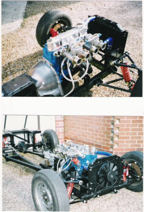
Now for the engine, I had already been seduced by the sight and sound of a 1600 x-flow with twin 40DCOES! So I went to see Dave of RPM who built my mate Bobs Chevy V8’s that are in his toys. We had a chat and decided on 1640cc all steel rocker shaft and gear, nice lumpy cam, gas flowed and ported head, baffled sump, uprated oil pump and competition clutch, there is more but this was all I could take in at the time! All in all the power should come in at 3000 - 6500rpm which for fast road work should provide a nice even power band. Dave is a very accomplished engineer as his track record proves, and being very methodical, likes to take his time, which is what you want when you are trusting someone to build you a strong reliable engine. I wasn’t in much of a rush, Bob put it another way when he said he’s very good, but does faff about! It was April 2001 so the engine should be ready by September that should leave plenty of time for faffing!! The Hamilton Build Project Part 5:
So
back to my build, the last chapter saw the chassis painted and rolling
and the engine being built by Dave at RPM Engineering. So now I had the
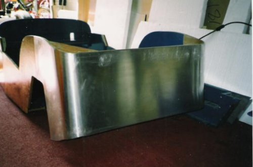
chance to concentrate on the job I feared the most, the skinning of the
body tub. Like
the majority of builders, I had no experience of working with sheet
aluminium. I had only the manual (Ha!), and the experience of the other
members in the club,(which was worth it’s weight in gold!).The pressure
was on, as any mistakes made now would be on show for all to see!
I
used the paper patterns for the body tub as templates onto plain
wallpaper with an extra 10-12 mm added where the edges were to fold
over. Cutting the ali was done with a pair of tin snips and a jigsaw
for the longer cuts. Another tip was to use a 2inch sheet of
polystyrene clamped to the underneath of the ali, to stop the jigsaw
vibrating and jumping around, so a nice even cut was achieved. Also
with the tin snips, I was advised to only cut with the first half of
the blades. As a complete ‘snip’ of the blades would distort the ali as
they cut. With this advice the cutting out of the ‘skin’ went smoothly.
After a quick rub with 360 grit emery paper to remove sharp edges and
swarf they were ready for fitting.
The
only areas of the skinning that were trying to be difficult were the
back panel which folds around onto the middle of the rear wheelarches
and the scuttle, the key seemed to be measure, measure, line up,
measure again, line up, then stick!. The scuttle was going to be the
most difficult part to do. I remember one member of the club having
three attempts at his! I however, had a rather cunning plan! I really
wanted a neat finished edge where the scuttle meets the side flanks. I
wasn’t keen on having exposed screw heads, and I didn’t want to rely on
just the adhesive, as the scuttle is ‘sprung’ in at the sides. So the
following plan came together. I rebated the body side flank where the
scuttle edge met (see diagrams). Then when the scuttle was formed and
glued over the dash top it was gently beaten into the rebate and glued
and screwed into place. The rebate was then filled with body filler,
sanded smooth, and then the side flank panel would butt up against the
bottom edge of the scuttle. This gave me the clean edge that I was
looking for without exposed screw heads.
When
it came to the adhesive I was surprised at how easy it was. I was very
careful to align the panels properly and knew that you only get one
shot at it! But it all went rather well with just the bare minimum of
swear words! So well that I rather enjoyed this part of the build!
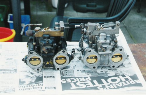
A
trip to Dave at RPM Engineering to see how my engine was coming along,
saw me coming back with a pair of Weber 40DCOE’s and an RS2000
aluminium bellhousing ,which would fit directly to the sierra 5 speed
type 9 gearbox that I had got from a breakers. The Webers were already
jetted for a 1600 crossflow! They were laying around his workshop, left
over from other projects, now they were part of mine! One thing that
struck me as odd though was that they were painted matt black. This, I
later found out, was to help dissipate the heat from the engine to stop
the fuel from evaporating! Well, you learn something new every day!
With
the engine still being ‘faffed’’ with, I decided to paint and put on
the fuel tank. I also decided were to mount the fuel pump and made up
two suitable brackets. The fuel pump I used was a Facet solid state
competition. It came in a kit with anti vibration bobbins and a filter.
I bought this from Burtons along with a set of Magnecore electrosports
blue 8mm leads, side exit distributor cap, Lumenition electronic
ignition module and a Bosch high power coil with ballast resistor. I
know that I didn’t need all of this just yet, but while I had the
money, I was like a kid in a sweet shop! The Hamilton Build Project Part 6:
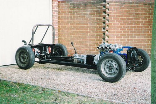
Now
that the body tub was skinned, the chassis had been painted and was now
rolling with its Cortina uprights, (not many of those about now!),
bought from a good old fashioned scrap yard, you remember them don’t
you, where you were allowed to climb all over the old cars before the
Brussels safety police got involved! I completed the set up with a new
steering rack bought from a local motor factor. This went on with no
bother, fitted with new rubber mounts. I purchased the extension piece
from BWE, but the wheels seemed to splay outwards too much .So I ended
up cutting the thread down on the track rods to achieve a more normal
stance. I t was
September 2001 and my engine was ready! My 1640 crossflow with Karl
Schmit pistons, all steel rocker gear, polished and ported unleaded
head with one piece valves, competition big end bolts, duplex timing
gear A1 fast road camshaft, uprated oil pump, modified distributor
(Optronic Lumenition electronic ignition) lightened flywheel, uprated
clutch, baffled sump and twin 40 DCOEs all mated to a 5 speed type 9
gearbox with its RS2000 alloy bellhousing. Dave brought it round, and
it went in sitting on new Pinto engine mounts. With the body off it was
no problem at all. We linked up an oil pressure gauge, battery etc. and
the plan was to turn the engine over to get the oil pressure up before
the fire up. This turned out to be a bit of a kerfuffle, as my battery
gave up! So Dave got the battery from his van, which also gave up!!
With no oil pressure showing on the gauge the only option left was to
tow it, but with light fading and the minor fact that I had no brakes!!
We decided to call it a day .I was disappointed to say the least, but
the engine was in and to fire it up would have to wait for another day.
I was eager to
start my new engine, but with work and family commitments, things
ground to a halt. Dave had taken a job with Virgo motorsports which
involved looking after their stable of race prepared cars for
corporate days, which included a Ferrari 360, an ex F1 car and their
GT1 Moseler which was competing in the Dutch Supercar Challenge. The
latter saw him travelling to all the major circuits across Europe, what
a job!! Unfortunately for me, this meant that my engine had to wait! During
the time that Dave was away I managed to plumb in the brake lines,
modify the mount for the gearbox. With the gearbox mounted I could now
get my propshaft fabricated. I used a company called Dynoprop
Balancing, after a phone call, all they needed to know was the
measurement between the end of the gearbox and the face of the diff
flange, also what gearbox I was using. I took down the old Escort
propshaft, so they could use the end flange that fixed to the diff
flange. Within a week I had my new propshaft, painted and ready to fit.
It was fitted in no time at all …perfect!
For
the rollover bar, I wanted something different to what BWE were
supplying. I had already had an extra mount welded to the chassis to
give me a two rear stays, like a Westfield/Caterham. So after taking
measurements from Pete’s car I decided to have one made up by local
steel suppliers/fabricators. The main ‘hoop’ was made using 3mm wall
gas tubing with an external diameter of 48mm; this was bent to my
requirements. I had Pete cut me some 5mm steel plate into four 120mm x
100mm pieces; these were matched and drilled to suit the mounting
plates on the chassis and then bolted to them. Now that I had a solid
fixture, I could place the roll bar in the centralised position, and
when happy, weld it up. After a phone call, Jim came round to do the
honours with the welding. The stays had an external diameter of 33mm
and after the main hoop was welded, I could now get these welded on as
well. They had been measured and ‘birdmouthed’ in a previous mock-up
providing a tight fit. I still had to weld in another piece of tubing,
bracing the main hoop, for the harness mounting eyelets. However this
would have to wait, as I had to comply strictly with SVA requirements,
and in order to do this accurately I would have to have seats.
I
also found the time to sort out a cooling system. Samco blue hosing was
used with stainless steel jubilee clips, and I had planned to use the
radiator that had come with the broken 1300 Escort. The combination of
a narrow ali lined engine bay, fibreglass nosecone, close fitting ali bonnet and a modified engine, was all going
to add up to one very hot and bothered Locust! So I was in no doubt
about having to upgrade this radiator. I took it to Essex Radiators who
ran a pressure test to confirm that was blocked and had a leak! – Oh,
and it wasn’t from a 1300 MK2 Escort, it was from an 1100 MK1! So it
turned out that the donor had a donor radiator! This didn’t really
matter as I knew that it would be taken apart anyway. The good news was
that the top and bottom tanks were good and could be reused along with
a new double core, good enough to cool a touring car so they said. The
good thing about using the tanks was that it saved money and it meant
that the radiator would keep its original dimensions, which in turn
meant that it could fit totally upright inside the nosecone. While this
was being done, I set off to my favourite scrap yard, (Kirby’s in
Rochford), to find a suitabl electric fan man enough to do the job properly.
I came across one big mother of a fan on a 2.8i Granada Ghia x MK2
(where did all of these go? I remember lusting after one of these, way
back when insurers would only laugh when I asked for a quote, on
account of my youth!!). This would do the job, and it came with
mounting brackets. To fit this I made up a simple sub frame which was
welded, (by Jim again), to the top and bottom front cross members of
the chassis using 20mm box section. Flat 40mm x 3mm bar was then welded
to this to provide a mounting face to attach the radiator and fan to.
The radiators’ filler cap was blanked off, as I was going to use a
Fiesta MK2 remote filler/thermostat housing which incorporated a fan
temperature switch. This was purchased from Burtons.
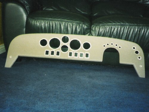
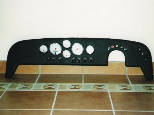
With the body now secured it was really starting to look like a Locust! With the body tub mounted, the engine fitted and the cooling system plumbed, it was about time to tackle the dashboard and wiring loom. For the instruments I originally bought a dashboard full of Smiths Triumph Dolomite Sprint gauges. But after seeing the gauges used by Nigel Dean in his Westfield build in Which Kit magazine, I decided to give ETB Instruments a call and ended up buying a full set all electric and with SVA compatible bezels. Thanks to Ebay I managed to get back the money I had spent on the Triumph dash, and a bit more!! With the loom I freely admit to cheating and buying a custom made loom from Trust Electrical. The reasons for this were that I was not that confidant with auto electrics and really didn’t want the car going up in smoke due to my lack of knowledge! I rang Trust with a list of requirements for the loom and they built the loom using all the correct relays, fuse box , switches etc. and left the wiring for the components and lights overlong to enable me to route the loom in the neatest way. Although this wasn’t the cheapest option it was quicker and I was able to have the loom ready to fit. With the instruments delivered I turned my attentions to the dashboard. I had looked at a lot of seven style cars, some like the Dax Rush which had an innovative design, while others had gone for a more original look such as Westfield, Tiger and Caterham. Although I preferred the original look I still liked the ‘custom’ looks but with the small dimensions of the Locust cockpit I soon realised my layout would be best suited to a more traditional layout. The original plans for cutting the dashboard from the ¾ inch plywood were, as I found out, next to useless. This was because the scuttle top was formed around the firewall and being ‘sprung’ in at the sides. Depending on how sprung it was dictated the general shape of dashboard. Looking at other Locusts I could see how this varied from car to car. I decided to use MDF as this would be easier to cut and sand into shape. I started as always with a cardboard template which was transferred to the MDF. I then worked out what angle I wanted it to sit at and used 2.5mm thick 20mm x 20mm aluminium angle screwed to the body flank sides. This enabled me to bolt the dash in place and marked out where it needed to be cut and sanded into shape, to provide extra stability I fixed self-tapping screws at equal distance around the scuttle top which eventually would be hidden by using press studs so if I wanted to fit of a tonneau Now I had a ‘blank’ I cut out paper templates representing the switches and instruments and spent what seemed like forever moving them about to get the desired look. Once I was happy with the layout the construction could begin. The dash was ¾ inch thick and I wasn’t happy cutting out individual holes for the switches and clocks, as the switches I was using were the popular ‘Delta’ type they would not fit, as they are ideally suited to much thinner material. The same was true for the clocks also. I decided to cut out sections where the clocks and switches were going to be positioned. This left me with a sort of frame with which I decided to skin with 2mm aluminium this enabled the clocks etc; to fit properly and gave me the opportunity to obtain the correct radius for the bottom of the dash for the SVA , for this I used a broom handle as a former. The holes were cut with a set of hole cutters and the finished with a file to obtain a snug fit. The square holes for the switches were first chain-drilled then carefully filed, which was very tricky and needed all of my concentration!
To seal the MDF I coated with a couple of coats of PVA glue mixed about 70/30 with water, using the 3M Fastbound I glued the aluminium face to the MDF blank. To enable the clocks and switches to sink a little into the dash, I covered it with 2mm foam sheet glued using spray adhesive. This was a belt and braces approach, as I had SVA compatable bezels on the instruments and used compliant switches, but as I had planned to do throughout the build, decided just to make sure! With this done the whole lot was covered in black vinyl secured using the spray adhesive again. I had already bought a Dino 11 inch SVA compatible steering wheel complete with collapsible steering boss and protective centre pad this was fitted prior to finishing the dashboard to ensure the correct clearance was obtained. Beneath the centre of the dash I made up a simple panel out of aluminium to house the starter button, electric cooling fan and the ignition key switch. This was fixed to the gearbox side flanks with a couple of brackets made from aluminium. The layout shown in the pictures has changed since, but the method used was exactly the same, and as always it was faster and easier the second time!
The next job was the wiring loom; this went in with the minimum of fuss, which is rare when building a Locust! The instructions given with the loom were excellent and easy to follow, even for me! My extras which I had requested included feeds for footwell lights, electric fan override switch and the heated windscreen switch which was incorporated into the two speed heater switch, position one for heated screen the second position for the interior heater. The biggest headache with this was deciding where the banks of relays were going to be positioned! With the dashboard completed I thought about the exhaust, I knew that Westfield did a complete exhaust for the X-flow in stainless and I knew that this usually passed the SVA for rounded contactable edges and noise levels, so I gave them a call. The exhaust duly arrived, but there was a problem, the headers were not long enough. The downpipe was hitting engine mount bracket and was too close to the starter motor.So I took some measurements and the headers down to Powerspeed a firm in Kent who manufactured custom stainless exhausts. They made up a new set to my spec using the Westfield one as a template, but extending the lengths. A week or two later I went and picked them up, and seeing as Leeds castle was just down the road decided to take the kids out for the day, well it was the school holidays and they were a bit young to be left on their own!! My exhaust measurements were spot on, it fitted like a glove. I finally caught up with Dave from RPM he had a couple of days free and so we arranged the first start up of the engine. This time I had a fully charged battery and he also brought a tow rope! I had previously turned the engine over with the starter motor to try and get the engine oil pressure up but only succeeded in running the battery down. I mentioned this to Dave when he arrived and we tried again, but the pressure hardly moved on the gauge and the warning light refused to go out. To save the battery we decided to tow it, now that I had some brakes! It felt great driving down the road, despite the fact I was being towed, as it was the first time that the car had been off the driveway! After a quick trip down the road and back we saw a healthy oil pressure on the gauge and the warning light extinguished. Now to start it up. At first the starter motor seemed to struggle, and then the engine burst into life on the third go with a little tweeking with the carbs and the timing set it settled down to a slightly high idle speed. As with these special moments in life us petrol heads tend to get a bit carried away with all the excitement and thrill of it all, and I must admit totally failed to notice the petrol trickling from the carb trumpets! Luckily Dave (who is used to such excitement) did notice and we shut off the engine. After further investigation we came to the source of the leak was down to over fuelling by the fuel pump. The Facet solid state pump was a bit fierce and the next pump down which put out 3.00 – 4.5 psi was the one to go for. With that panic over we started it up again and while taking the revs up and making adjustments to the carbs we heard a loud pop followed by a wet garage floor!! I thought a rad hose had let go, but after shutting off the engine again we discovered that a core plug had popped. Luckily I had a spare and Dave brought the tool used to insert it. With that now fixed and the engine tested we packed up and I had a smile on my face for the rest of the day!
Richard Hamilton | ||||||||
|
|
||